In the evolution of modern infrastructure, the precast segmental bridge stands as a marvel of industrial efficiency. Unlike traditional monolithic casting, segmental construction breaks a bridge deck down into manageable “slices”—discrete concrete boxes that are assembled on-site.
However, the shift to assembly-based construction places the engineering burden on logistics and mechanical precision. The integrity of a segmental bridge depends entirely on how these segments are handled by heavy duty gantry crane. Whether using the balanced cantilever method or span-by-span assembly, the choice of Launching Gantry or Lifting Frame determines the project’s heartbeat.
The Precision Mandate: Challenges in Segmental Handling
Lifting a bridge segment is fundamentally different from a standard beam lift. A segment is typically a hollow box girder with complex geometry and internal ducts for post-tensioning.
The primary risks are geometric deformation and surface spalling. If a Segmental Lifting Frame supports the piece incorrectly, the thin “wings” or the bottom slab can crack under self-weight. Moreover, because segments must fit perfectly with only a thin layer of epoxy between them, the lifting crane must allow for six degrees of freedom—pitch, roll, and yaw—to achieve sub-millimeter alignment.
1. Equipment Selection: The “Workhorses” of Bridge Construction
The construction sequence dictates the type of gantry crane required. There are three primary machines used in high-end infrastructure projects:
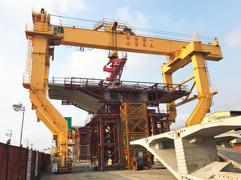
A. The Launching Gantry (Overhead Bridge Builder)
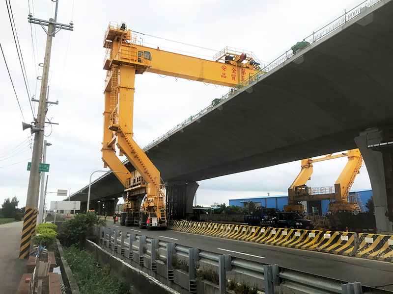
For long, multi-span viaducts over water or existing traffic, the Launching Gantry (also known as a beam launcher) is the most efficient choice. These are massive steel trusses that “walk” from pier to pier.
-
Strategy: The gantry supports the entire weight of a span while segments are fed to it—either from the completed deck behind it or from ground level.
-
Precision Factor: Modern Launching Gantries utilize automated winches that adjust the segment’s orientation in mid-air, ensuring the match-cast faces align perfectly before epoxy application.
B. Segmental Lifting Frames (Deck-Mounted)
On balanced cantilever projects, where the bridge grows outward from a central pier, Lifting Frames are mounted directly on the leading edge of the deck.
-
Strategy: These frames lift segments vertically from a barge or a Straddle Carrier below. As each segment is glued and tensioned, the frame is moved forward to the new “tip” of the cantilever.
-
Efficiency: This method eliminates the need for a full-length gantry, making it ideal for high-altitude bridge decks or deep valley crossings.
C. Rubber-Tyred Gantry Cranes (Yard & Site Logistics)
In the precast yard and for ground-access assembly, the rubber tyred gantry crane provides the mobility that fixed cranes lack.
-
Strategy: For segmental bridges, these carriers must be equipped with specialized “C-hooks” or internal spreaders. They transport the segments from storage to the “pick-up” point under the Launching Gantry.
2. Rigging Schemes and Stress Distribution
How a segment is “held” by the hoisting mechanism determines its structural health. Engineers typically employ one of two primary rigging strategies:
Internal Spreader Beams
By placing a spreader beam inside the hollow cell of the segment, the lifting force is applied from the “inside out.” This leaves the external road deck clear for workers.
-
Risk Mitigation: The lifting points must coincide with the internal diaphragms to prevent “bursting” stresses.
External Lifting Bars (Threaded Bar Systems)
High-strength threaded bars (such as Dywidag or Macalloy systems) are passed through pre-cast holes in the segment’s top slab to connect with the Lifting Frame above.
-
Strategy: This provides a rigid connection, essential when the segment needs to be tilted to match the specific longitudinal grade of the bridge design.
3. The Balanced Cantilever Strategy: Maintaining Equilibrium
One of the most delicate operations involving a Bridge Construction Crane is the Balanced Cantilever Method. Segments are added to opposite sides of a pier in a strict sequence to prevent the pier from “tipping.”
-
The Out-of-Balance Limit: Engineering specs define the maximum “out-of-balance” force. Usually, this is limited to the weight of one segment.
-
The Synchronized Lift: Advanced projects use twin Lifting Frames that operate in sync. If one frame’s winch lags, the system automatically adjusts to ensure the dynamic loads on the pier remain neutralized.
4. Precision Alignment and Geometry Control
Lifting the segment is only half the battle; the other is the “joining.”
As a segment is hoisted into position by the Gantry Crane, surveyors use total stations to track its 3D coordinates.
-
Fine-Tuning: Hydraulic cylinders on the Lifting Frame allow for “micro-movements.” This is critical; if one segment is 2mm off-center, that error compounds. By the 20th segment, the bridge could be centimeters out of alignment.
-
Epoxy Management: The hoisting system must bring the segments together and apply temporary post-tensioning within the epoxy’s “open time” (often 30–60 minutes).
5. Safety Protocols for Infrastructure Lifts
Lifting 100-ton segments over active highways requires a “fail-safe” mindset.
-
Wind Speed Thresholds: Operations with a Launching Gantry are usually prohibited when wind speeds exceed 12 m/s. The large surface area of a box girder makes it act like a sail.
-
Redundant Braking: Bridge cranes must be equipped with secondary emergency brakes acting directly on the winch drum.
-
Dynamic Load Factors: All calculations for the Straddle Carrier or Gantry include a “Dynamic Factor” (typically 1.1 to 1.5) to account for vibrations during start/stop movements.
6. The Future: Digital Twins and Automated Gantries
The next frontier is the integration of Digital Twins. Before the Launching Gantry lifts a single piece, the entire sequence is simulated.
During the actual lift, sensors on the Lifting Frame feed data back to the digital model. This allows engineers to predict how the bridge deck will “sag” as more weight is added, adjusting the coordinates of the next segment to compensate in real-time.
Conclusion
Lifting strategies for precast segmental bridges are an exercise in controlled power. Brute force is useless without absolute precision. By combining robust Launching Gantries, specialized Lifting Frames, and mobile Straddle Carriers, engineers weave massive concrete components into seamless infrastructure.
For the project manager, success is found in the quiet, steady rhythm of the lifting equipment—where hundred-ton segments are moved with the delicacy of a watchmaker’s hand. As global demand for rapid infrastructure grows, these advanced crane strategies remain the backbone of the industry.